Reading Electrical Circuit Diagram - ITI ED 1st Year

Reading of Electrical Circuit Diagram: ITI Engineering Drawing 1st Year for Electrical Trades is here. Short and Open circuits, Voltage divider

Reading of Electrical Circuit Diagram 
Reading of Electrical Circuit Diagram: ITI Engineering Drawing 1st Year for Electrical Trades is here. Short and Open circuits, Voltage divider circuit, Series type ohmmeter, Inductor connection, Capacitor connections.

Electrical Circuit Diagram Reading

Shorts in parallel circuit

Q1. Find the short circuit in parallel circuit given below?
short circuit in parallel

Ans.  In this circuit diagram shows a parallel circuit with short between points ‘a’ and ‘b’

Q2.  How to find the short circuit in a resistance?
Ans. To find a short circuit in a resistance, add a voltmeter in parallel to the resistance. If the resistance is short, the voltmeter will not give any reading.

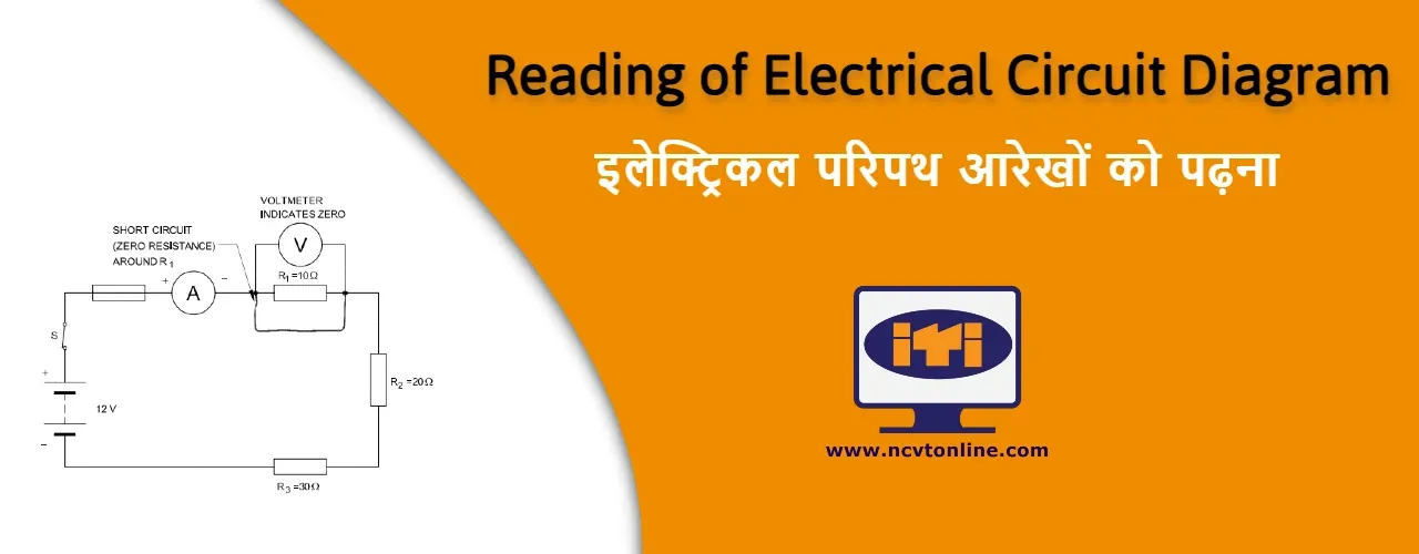
Open circuit in series circuit

Q.1 How to find the open circuit in series circuit?

Q.2 Find Voltmeter reading in series open circuit given below


Ans1. An open circuit results whenever a circuit is broken or is incomplete, and there is no continuity in the circuit. In a series circuit, open circuit means that there is no path for the current, and no current flows through the circuit. Any ammeter in the circuit will indicate no current.

Ans2. 18 Volt, Because the circuit is open, the voltmeter will show the supply voltage.

Series type Ohmmeter

Q1. What type of ohmmeter is used in Fig 17?

Series type Ohmmeter

Ans1. Series type ohmmeter


Q2. What is the purpose of range switch in Multi Range Series type ohmmeter circuit?

Multi Range Series type ohmmeter

Ans2. In the choice of resistance range for measuring resistance of different values

Voltage divider circuit

Q. What type of circuit Diagram is shown in below?

Voltage divider circuit

Ans. Voltage divider circuit


Inductor connection Circuit Diagram

Current flow through a coil connected to a DC source is limited by the wire resistance of the coil only (Fig 22a) Current flow through the same coil connected to an AC source is limited by the wire resistance and the inductive reactance (Fig 22b)
Inductor connection Circuit Diagram

Inductor series connection

Q. What is the total inductor value?

Inductor series connection

Ans. 5+2+10+1 = 18mH

Inductor parallel connection

Q. Find the total inductor value?

Inductor parallel connection

Ans. 1/ Lt = 1/10+1/5+1/2 = 1.25mH

Capacitor connection Circuit Diagram

Capacitors are connected in groups in two ways.

1. Capacitor parallel connection

When capacitors are connected in parallel, the total capacitance is the sum of the individual capacitances, because the effective plate area increases. The calculation of total parallel capacitance is analogous to the calculation of total resistance of a series circuit.
Capacitor parallel connection


Q. What is the total capacitor value?
Capacitor in parallel

Ans. Total capacitor value = 25+50+75+100 = 250 uF

2. Capacitor series connection

When capacitors are connected in series, the total capacitance is less than the smallest capacitance value.
Capacitor series connection


ED 1st Year Other Topics for Electrical Trades

Electrical Trades - Electrician, Wireman, Electroplater, Lift & Escalator Mechanic, Electrician Power Distribution. Select Engineering Drawing 1st Year topic from below.

Post a Comment